Robot Controller
The robot controller component implements a general robot controller, capable of executing a variety of instructions. The robot controller automatically computes the forward and inverse kinematics and can seamlessly handle closed kinematic structures. Every type of industrial robot is supported. The axes that make up the robot are automatically detected by the robot controller. Please see the API documentation if you would like to learn more about how to create scripted programs.
If the robot contains joints for a tool (such as a mechanical gripper), you can manually specify the axes to be solved through the joints property of the component, which allows you to exclude the joints for the end effector so that they aren’t solved by the robot controller when computing the inverse kinematics.
Properties
The robot controller component properties that are accessible through the inspector.
TCP
The entity that serves as the Tool Center Point (TCP) for the robot. This entity must be a child of the robot. The Robot TCP component may be used to accurately position the TCP by selecting a feature from the mesh. If the entity contains a Robot TCP component, then this component will be used to determine the position and orientation of the TCP. If the entity doesn’t contain a Robot TCP Component, then the transform of the TCP entity will be used to determine the pose instead.
Programs
The list of robot programs. A robot controller can have multiple programs. Each program must have a case-insentitive unique name. If the program is called Main, then this program will be executed automatically. Programs contain an ordered list of instructions that get executed. The following instruction types are available:
- Empty: An empty (placeholder) instruction that performs no action.
- Pause: Instructs the controller to pause execution of the program for a set number of seconds.
- Linear Move: Instructs the controller to perform a linear move (MoveL, LIN) to the specified target entity.
- Joint Move: Instructs the controller to perform a joint move (MoveJ, PTP) to the specified target entity.
- Path Move: Instructs the controller to perform a path move (MoveP).
- Set Speed: Instructs the controller to change zero or more motion parameters.
- Set TCP: Instructs the controller to change the currently active TCP to the specified entity.
- Await Signal: Instructs the controller to pause execution until the specified signal reports a particular value.
- Set Signal: Instructs the controller to set the specified signal to a particular value.
- Call: Instructs the controller to call the specified program.
- Conditional Call: Instructs the controller to call the specified program if the specified signal reports a particular value.
- Call Script: Instructs the controller to call the specified scripted program.
Joints
The optional list of joints to be controlled by the robot controller. If no joints are specified, then the robot controller will automatically detect all the joints on any descendant entities. If the robot contains a jointed tool (such as a mechanical gripper), then it is necessary to provide the list of joints that should be controlled. This ensures that the robot controller will not attempt to control the joints belonging to the tool.
Linear Speed
The maximum/target linear speed for the TCP that the robot controller tries to achieve when performing linear moves.
Linear Acceleration
The linear acceleration/deceleration for the TCP that the robot controller should use when performing linear moves.
Angular Speed
The maximum/target rotational speed for the TCP that the robot controller tries to achieve when performing linear moves.
Angular Acceleration
The rotational acceleration/deceleration for the TCP that the robot controller should use when performing linear moves.
Joint Speed
The multiplier to apply to the target speed of all joint motors when performing joint moves. For example, a multiplier of 2.0 (200%) will allow the motors to move up to twice as fast as the initial target speeds set on the motors.
Joint Acceleration
The multiplier to apply to the acceleration/deceleration of all joint motors when performing joint moves. For example, a multiplier of 0.5 (50%) will cause the motors to accelerate/decelerate half as fast as the initial acceleration/deceleration set on the motors.
Gravity Compensation
Whether to apply gravity compensation to the robot joints. When enabled, it causes the gravitational force to be disabled on any links that are driven by the robot controller. It can improve stability and reduce constant joint error. However, please note that the torque reported by the motors will exclude the torque required to compensate for gravity. This property is enabled by default. You should disable gravity compensation if you want to report accurate joint torques.
Kinematic
Whether robot motion is applied directly using forward kinematics. When enabled, the robot links are made kinematic on initialization. This property is enabled by default. You should disable the kinematic property for accurate stall detection and motor torque reporting.
Instructions
The robot controller supports a wide range of instructions that can be executed.
Empty
The empty instruction is used as a placeholder. It performs no action when executed.
Pause
The pause instruction causes the robot controller to pause execution for a fixed number of seconds.
Servo Move
The servo move (MoveServo) instruction commands the robot controller to move all joints to the specified positions. The robot will attempt to move at the target speed of the most limiting joint, such that all joints arrive at the same time. The path that the TCP takes is somewhat unpredictable, though still deterministic. It is particularly useful if you want to reposition the robot, such as moving an external linear axis, without moving any of the other joints. You select a list of joint value pairs for joints that are controlled by the robot controller. The value represents the target position for the motor that drives the joint.
Joint Move
The joint move (MoveJ, PTP) instruction commands the robot controller to perform a joint movement to the specified target entity. The path that the TCP takes is somewhat unpredictable, though still deterministic. The inverse kinematics for the robot are solved, then the joints are commanded to move to the positions that were solved. The speed which the joints move is determined such that all joints arrive at their target positions at the same time, whilst ensuring not to violate any speeds/accelerations set on the motors. However, keep in mind that the Joint Speed and Joint Acceleration multipliers get applied, which may be used to adjust the maximum speed and acceleration of the motors.
It is possible to select a joint move robot solution through the UI, which solves the inverse kinematics at design time, instead of when the joint move instruction is executed. A preview of the robot being solved to the target pose will be shown as you hover over the solution in the dialog window. This can be used to improve runtime performance and ensures that the path followed by the TCP is more predictable/controllable.
Linear Move
The linear move (MoveL, LIN) instruction commands the robot controller to perform a linear movement towards the specified target entity. The TCP will be moved along a line from its current pose to the target pose. Note that linear moves may encounter singularities. The speed at which the TCP moves through world space is governed by the Linear Speed and Linear Acceleration properties. The rotational speed of the TCP is governed by the Angular Speed and Angular Acceleration properties. The initial target speeds and accelerations set on the motors are ignored.
Path Move
The path move (MoveP) instruction commands the robot controller to move along a path. The path that the TCP takes is specifed by selecting a curve using the feature selection tool. The curve will be automatically detected as either a line, polyline, circle, arc or a composite curve that consists of lines and arcs. The path move will discretize the curve according to the discretization parameter specified. The discretization parameter controls the number of points in the discretized curve. You can specify both the start point and length of the path as a percentage. The default value for the start is 0% and for the length is 100%.
The rotation of the TCP along the path can be one of two modes:
- Constant: Orientation is constant along the path.
- Follow Curve: Orientation follows the path.
The global rotation offset can be used to offset the rotation of the frames along the path, for all points in the discretized curve. The local rotation offsets can be used to offset the rotation of the frames along the path for specific points at a specified percentage along the path. The frames of the points between two local rotation offsets (e.g. local rotation at 20% and local rotation at 30%) are then spherically interpolated. If a point does not exist at the specified percentage in the discretized curve, a new point will be inserted at that position with the specified local rotation.
The reference frame is an optional entity that the path is attached to. This allows you to make the path local to the reference entity, instead of local to the robot controller. The reference frame enables simulation of workpiece positioners, so that when the positioner rotates, the selected curve rotates with it.
Arc Move
The arc move (MoveA) instruction commands the robot controller to move along an arc from the current TCP frame to the end target, through the position of an intermediate target. The intermediate target entity determines an intermediate point along the arc. The end target entity determines the end frame of the arc. 2 target entities must be provided to define a unique arc for the move.
The rotation of the TCP along the arc can be controlled using one of the following modes:
- Constant: Orientation of the current TCP frame is constant along the arc, ignoring the orientation of the intermediate frame and end frame.
- Follow Arc: Orientation of the current TCP frame stays fixed relative to the arc, ignoring the orientation of the intermediate frame and end frame.
- Interpolate: Orientation interpolates from the current TCP frame to the end frame, ignoring the orientation of the intermediate frame.
- Interpolate Through Intermediate: Orientation interpolates from the current TCP frame to the end frame, through the orientation of the intermediate frame.
If the targets are collinear, the robot controller will output an error. You cannot use a single MoveA instruction to move the TCP along a 360° full circle. You must either use two MoveA instructions or one MoveP instruction to accomplish a full circular move.
Set Speed
The set speed instruction can be used to modify the motion parameters of the robot controller during the execution of a program. The Enable property specifies which motion parameters should be modified. Note that multiple parameters may be modified by a single set speed instruction. This instruction is used to adjust the speed/acceleration of the robot for a particular sequence of moves.
Set TCP
The set tool center point instruction can be used to modify the active tool center point of the robot controller during the execution of a program. This is generally used to switch between multiple end effectors. For example, the instruction could be used to switch between two different suction cups. The TCP entity selected must be a descendant of the entity to which the robot controller is attached.
Await Signal
The await signal instruction is used to pause execution of the program until a specified signal on the robot controller’s IO reports a particular value. For example, this instruction can be used to pause execution until a sensor has been blocked. Note that you must first create a signal/variable on the robot controller’s IO.
Set Signal
The set signal instruction is used to set the value of a signal on the robot controller’s IO. For example, this instruction can be used to toggle the state of a suction gripper. Note that you must first create a signal/variable on the robot controller’s IO.
Call
The call instruction is used to instruct the robot controller to execute another program. This should be used to group related instructions into a separate program that can be called from the main program. For example, a program to pick and place an object can be called from the main program.
Conditional Call
The conditional call instruction is used to instruct the robot controller to execute another program if and only if a specified signal reports a particular value. This is used for branching (if statement) control. Note that you must first create a signal/variable on the robot controller’s IO.
Call Script
The call script instruction can be used to instruct the robot controller to execute a scripted program. Scripted programs should be used for advanced tasks, such as picking moving parts off a conveyor belt. For example, the moveLinearToIntercept() function that instructs the controller to perform a linear move to intercept the moving entity, cannot be called directly from the inspector UI, but can be called by a scripted robot program.
Creating a scripted robot program involves creating a scripted component that inherits from the RobotProgramComponent class. An example is provided below:
import { type RobotControllerComponent, RobotProgramComponent, SensorComponent, Entity, Future, Sequence, Handle } from "prototwin";
import { Frame, Quat, Vec3, Wait, Units, UnitType } from "prototwin";

export class MyScriptedProgram extends RobotProgramComponent {
    @Units(UnitType.Time)
    public pauseDuration: number = 0.5;
    public sensor: Handle<SensorComponent> = this.handle(SensorComponent);
    public target: Handle<Entity> = this.handle(Entity);

    constructor(entity: Entity) {
        super(entity);
    }

    public execute(controller: RobotControllerComponent): Future<void> {
        const sequence = new Sequence(false);
        sequence.add(() => controller.moveJoint(new Frame(Quat.identity, new Vec3(-0.2, 0, 0.2))));
        sequence.add(() => Wait.seconds(this.pauseDuration));
        sequence.add(() => controller.moveJoint(new Frame(Quat.identity, new Vec3(-0.2, 0, -0.2))));
        sequence.add(() => Wait.value(this.sensor.value!.io.state, true));
        sequence.add(() => controller.moveLinearToIntercept(this.target.value!, Frame.translation(new Vec3(0, 0.05, 0))));
        return sequence.run();
    }
}
To call a scripted program, you must first add the scripted component to an entity. The scripted program will then be selectable under the Script property of the call script instruction.
Please see the relevant API documentation that may be helpful when creating scripted robot programs:
- Robot Controller Component
- Robot Program Component
- Robot Program
- Handle
- Sequence
- Future
- Wait
- Frame
- Quat
- Vec3
It is also worth noting that you can use ProtoTwin’s AI assistant Torq to create scripted robot programs from natural language, instead of using the GUI or writing the code from scratch.
Constraints
Constraints can be specified on many different move instructions for the robot controller component such as joint move, linear move, path move, and arc move instructions. It allows selected joints to be constrained to specified values during the move. If you overconstrain the joints the robot controller may be unable to perform the required movement. Please note that constraints are optional.
For example, when selecting a joint move instruction, you can add a constraint to the 7th joint of a 6 axis robot mounted on an RTU (Robot Transfer Unit). Doing this allows you to specify an exact position for moving the linear axis. This may be desirable since the 7th axis adds a redundant degree of freedom, resulting in infinitely many solutions existing for the move. The solution picker for the joint move instruction may not list the solution you prefer, since infinitely many options exist.
Another example of constraints is keeping the robot TCP stationary while external axes are moved. This is made possible by using a linear move instruction and setting a constraint for the 7th axis. Also, for 7-axis robots like the Franka Research 3 with one redundant degree of freedom (DoF), joint constraints allow you to make the motion of the robot more natural. Without constraining a joint, or using the solution picker, the movements may be unnatural.
Weights
Weights are used to penalize the motion of certain joints, causing the inverse kinematics solver to prefer the motion of other joints. This is particularly useful for robots with redundant degrees of freedom, such as when using workpiece positioners or additional axes. Please note that weights are set globally on the robot controller component; not for each instruction, and that weights are entirely optional.
The weights are clamped to the range [0, 1]. A weight of 0 means that motion of the joint is not penalized. The weights are normalized by ProtoTwin’s inverse kinematics solver, meaning that the weights [J1 = 0.5, J2 = 0.25, J3 = ... = J6 = 0] are identical to the weights [J1 = 1, J2 = 0.5, J3 = ... = J6 = 0]. Setting all the weights to the same value is equivalent to not setting any weights at all.
ProtoTwin uses a null-space solver, which minimizes motion according to the weights. For example, consider a 6-axis robot arm welding with joints J1 to J6 and joint J7 for a workpiece positioner. The weights [J1, J2, ... , J7] = [1, 1, 1, 1, 1, 0] causes the robot solver to penalize motion for all joints of the robot arm equally, and instead favor moving the workpiece positioner. The solver will attempt to move the workpiece positioner as much as possible, to minimize the movement of the robot arm.
Weights are useful when you want to control the mechanism’s motion globally. You should prefer using constraints to weights, when you need to set the target position of the workpiece positioner to an exact value, such as 90°. Weights do not give you precise control over the exact positon of a joint. They allow you to minimize motion of certain joints compared to other joints.
You can calibrate the weights by clicking the ellipsis to the right of the component name, and then selecting Calibrate from the context menu.
Reordering
It is possible to reorder instructions and programs on the robot controller component by dragging the instruction or program and then moving it up or down the list. You may also move instructions between two different programs on the robot controller component.
IO
The IO signals for the robot controller component. Please see the RobotControllerIO API documentation for more details.
Error
A uint32 readable (output) signal that stores the error code. A non-zero value indicates that an error has occurred. The error codes are provided below:
- 0: No Errors.
- 1: Failed to complete a joint move.
- 2: Failed to complete a linear move.
- 4: Failed to complete a path move.
Configurable IO
The robot controller component has its own configurable IO, that allows users to add or remove IO points at design time. You can create a variable with a specified name, area (input/output), data type and value. You can then use direct connections to bind these signals to other signals, defined by a Entity/Component/Property path.
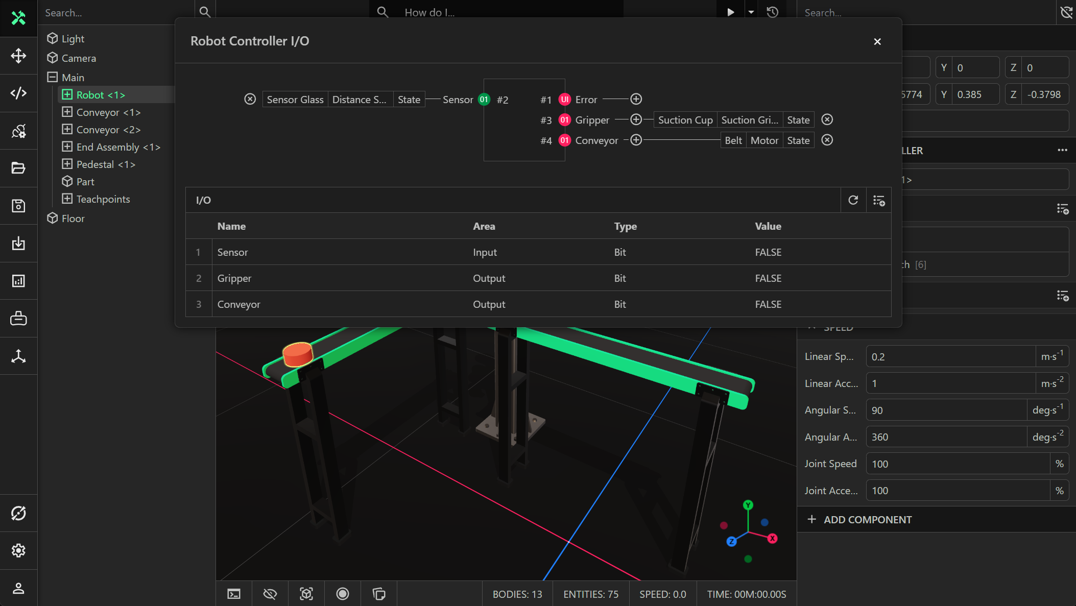
For example, in the screenshot above an input signal called Sensor and two output signals called Gripper and Conveyor were created. A direct IO connection was created between the Sensor signal and the state of the distance sensor component, so that the robot controller knows when the sensor is blocked. Another direct IO connection between the Gripper signal and the suction gripper component on the suction cup entity of the robot was created, which allows the robot to pick up the object. Finally, a direct IO connection between the Conveyor signal and the state of the motor for the conveyor belt entity was created. This allows the robot to turn the conveyor belt on/off.