Mitsubishi Connectivity
ProtoTwin Connect supports the MELSEC protocol for connection to Mitsubishi PLCs using MX Component.
MX Component Configuration
The Mitsubishi MX Component library is used to connect to all Mitsubishi PLCs. You must have MX Component installed on your PC in order to connect to the PLC. Before connecting to the PLC, you must use the Communication Settings Utility, installed as part of MX Component, to assign a station number to the PLC.
The precise steps to configure MX Component will depend on your PLC and how you wish to connect. The steps below describe the process for the FX5UC PLC. The configuration required for your PLC may vary slightly.
- Start the Communications Setting Utility and click the “Wizard” button.
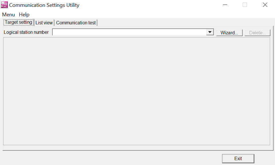
- Enter a station number for the PLC and click Next.
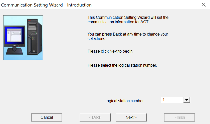
- Configure the communications settings for the PC and click Next.
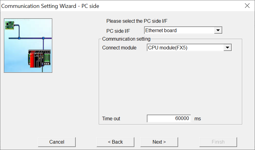
- Configure the communications settings for the PLC and click Next.
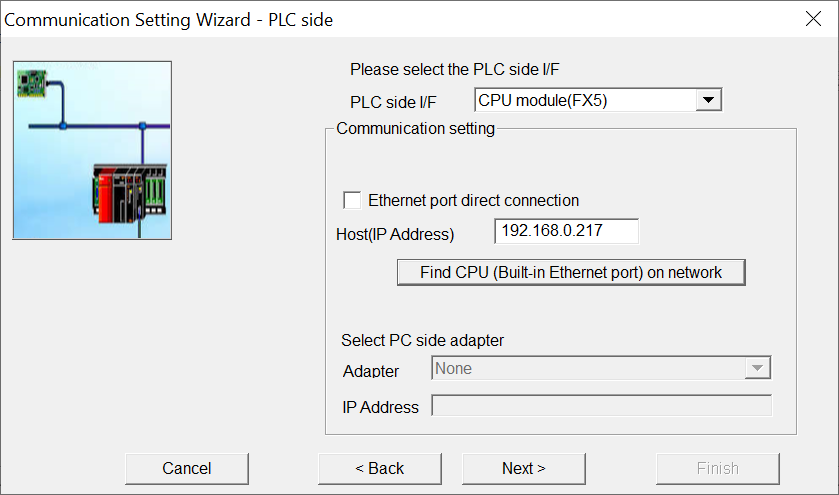
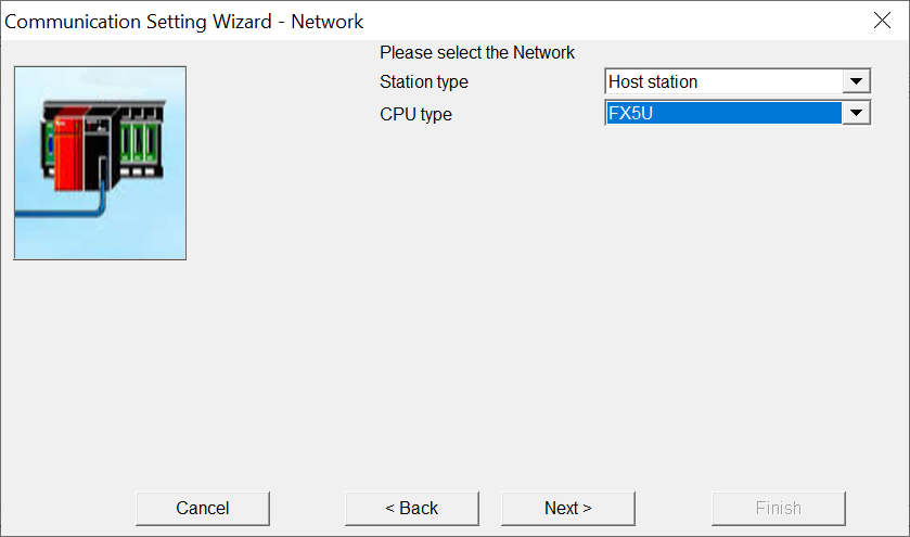
- Configure the CPU type then click Next and Finish.
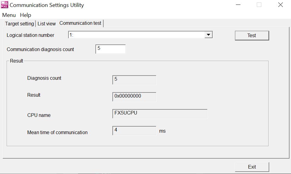
- Switch to the Communication Test tab, select the station and click Test.
Server Configuration
Click the Add Server button in the Servers tab of the IO Browser and configure the server as follows:
- Protocol: Select Mitsubishi MELSEC from the list.
- Name: Enter a (preferably) unique name, which will be used to identify the server.
- Host: Enter the static IP address of the PLC.
- Station Number: Enter the station number as configured in the Communication Settings Utility (see above).
- Scan Rate: Enter the desired scan rate, which is the interval (in seconds) at which ProtoTwin Connect will read and write tag values.
Areas
The following MELSEC address areas are supported:
- Input (X): Bit (Write to PLC)
- Output (Y): Bit (Read from PLC)
- Internal Relay (M): Bit (Read from PLC, Write to PLC)
- Latch Relay (L): Bit (Read from PLC, Write to PLC)
- Link Relay (B): Bit (Read from PLC, Write to PLC)
- Annunciator (F): Bit (Read from PLC, Write to PLC)
- Link Special Relay (SB): Bit (Read from PLC, Write to PLC)
- Timer Contact (TS): Bit (Read from PLC, Write to PLC)
- Timer Coil (TC): Bit (Read from PLC, Write to PLC)
- Timer Value (TN/T): Word (Read from PLC, Write to PLC)
- Retentive Timer Contact (STS): Bit (Read from PLC, Write to PLC)
- Retentive Timer Coil (STC): Bit (Read from PLC, Write to PLC)
- Retentive Timer Value (STN/ST): Word (Read from PLC, Write to PLC)
- Long Timer Contact (LTS): Bit (Read from PLC, Write to PLC)
- Long Timer Coil (LTC): Bit (Read from PLC, Write to PLC)
- Long Timer Value (LTN/LT): Double Word (Read from PLC, Write to PLC)
- Data Register (D): Word (Read from PLC, Write to PLC)
- Link Register (W): Word (Read from PLC, Write to PLC)
- Link Special Register (SW): Word (Read from PLC, Write to PLC)
- Special Relay (SM): Bit (Read from PLC, Write to PLC)
- Special Register (SD): Word (Read from PLC, Write to PLC)
Note that the Internal Relay (M) and Data Register (D) areas are most commonly used. A word is comprised of 16 bits, corresponding to a UInt16 or Int32 in ProtoTwin. A double word is comprised of 32 bits, corresponding to a UInt32 or Int32 in ProtoTwin.
Addressing
ProtoTwin uses the same addressing scheme as GX Works. Some examples are provided below:
- X0: The first input bit.
- Y1: The second output bit.
- M2: The third internal relay bit.
- D0: The first data register.
- D1.0: The first bit of the second data register.
- D1.15: The last bit of the second data register.
It is possible to store larger data types across multiple 16-bit registers:
- UINT32 at address D0: The 32-bit unsigned integer is stored in the data registers, occupying registers D0 and D1.
- FLOAT at address D2: The 32-bit floating point number is stored in the data registers, occupying registers D2 and D3.